· 4 min read
How to detect turbocompressor faults with vibration analysis
Unbalance, misalignment, rubs and instability each leave a distinct fingerprint in shaft vibration. Here is how to read them and act before a trip.
Andrés González
A turbocompressor almost never fails "out of nowhere." Weeks before a trip, shaft vibration is already telling the story: growing unbalance, alignment shifting with temperature, a seal starting to rub. The problem is that this information usually stays inside the protection system, which only checks whether an alarm or trip limit was crossed.
In this article we cover what a turbocompressor's instrumentation measures, which diagnostic tools to use, and what each typical fault looks like.
What is measured on a turbocompressor
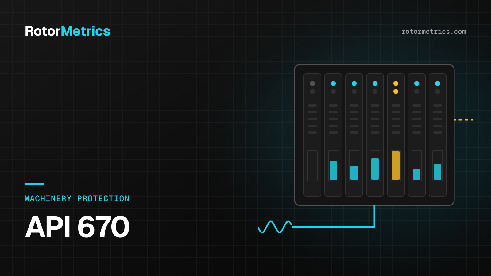
Most critical turbocompressors run on hydrodynamic (fluid-film) bearings and are instrumented per API 670 with:
- Proximity probes (two per bearing, 90° apart, called X and Y). They measure shaft motion relative to the bearing, in micrometers peak-to-peak (µm pp) or mils.
- Axial position probes, which watch thrust bearing wear.
- Phase reference (Keyphasor): a mark on the shaft that gives one pulse per revolution. Without it there is no phase, and without phase the diagnosis is only half done.
- In some cases, casing accelerometers for the gearbox.
The protection system (for example, a Bently Nevada 3500) compares the overall value against alarm and trip setpoints. That is its job and it does it well, but an overall value doesn't tell you what is happening, only how much.
The diagnostic tools
The probe waveforms are used to build the plots that actually explain the machine:
| Tool | What it shows | What it's for |
|---|---|---|
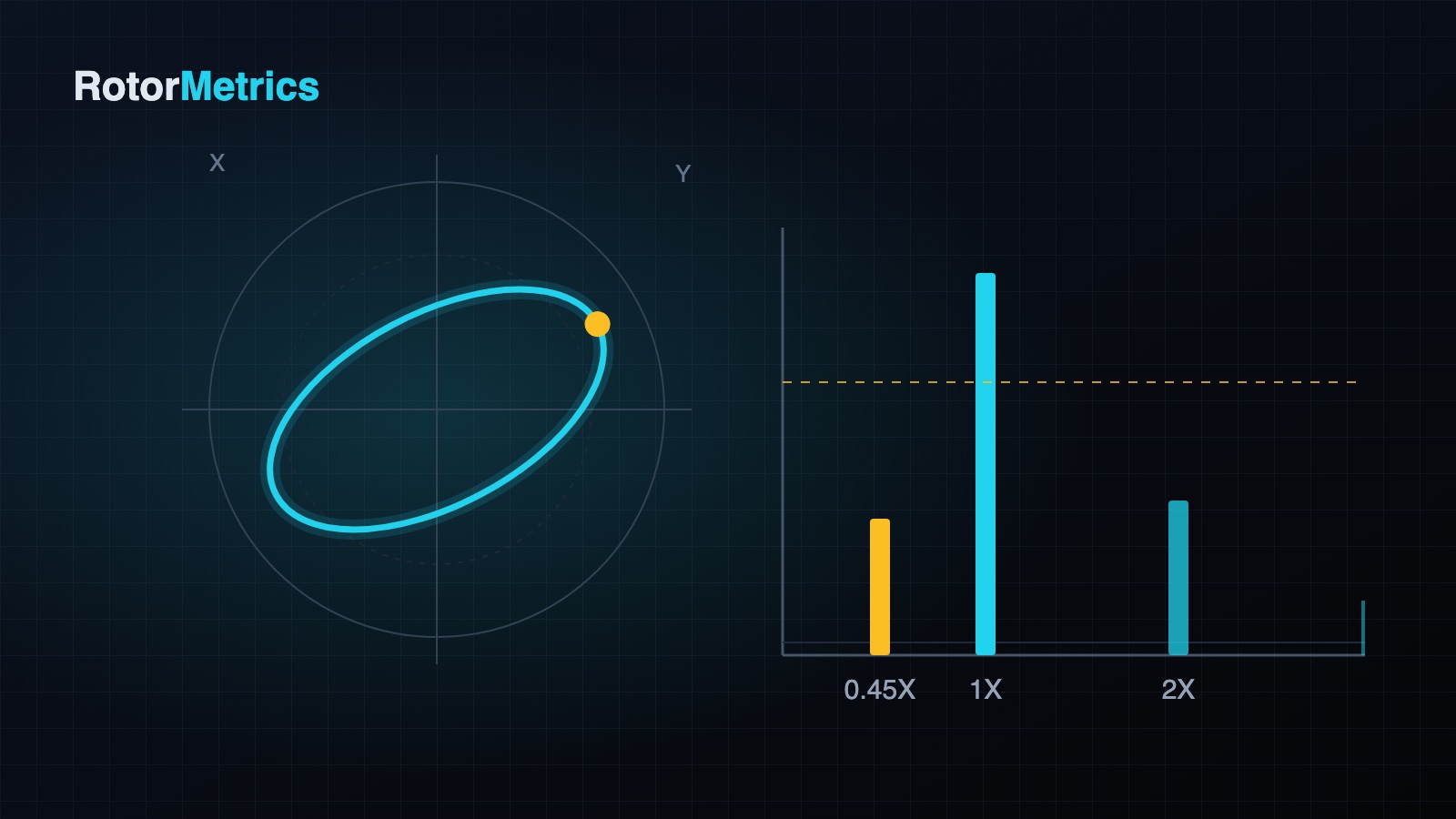
| Spectrum | Amplitude by frequency (1X, 2X, subsynchronous) | Separating faults that add up to the same overall value |
| Orbit | Path of the shaft centerline (X vs. Y) | Seeing the shape of the motion: elliptical, flattened, looped |
| Shaft centerline | Average shaft position inside the bearing | Detecting preloads, wear and load changes |
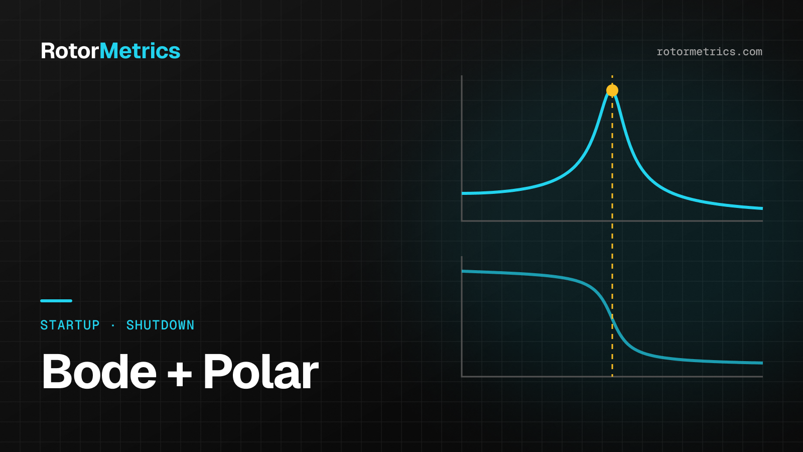
| Bode and polar | 1X amplitude and phase vs. speed | Finding resonances during startups and shutdowns |
| Trends | Evolution over days or weeks | Knowing whether something is changing, and how fast |
The golden rule: change is what matters. A machine that has always run at 40 µm and is still at 40 µm is less worrying than one that went from 20 to 35 µm in two weeks, even if neither has reached alarm.
The fingerprint of each fault
Try it: pick a fault and watch how the orbit and the spectrum change.
Unbalance
- The 1X component (once per revolution) dominates.
- 1X phase is stable and the orbit is elliptical, with one Keyphasor dot per revolution.
- Amplitude grows with speed, especially near critical speeds.
A change in 1X amplitude or phase at constant speed and load means something changed on the rotor: deposits breaking off, blade erosion or a loose part.
Misalignment and preloads
- 2X shows up alongside 1X, and the orbit flattens or takes a "banana" or figure-eight shape.
- The shaft centerline moves away from its normal position: the shaft is pushed to one side of the bearing.
- It usually changes with temperature, so it looks different cold and hot.
Rub
- The orbit looks truncated or clipped, with sudden changes in direction.
- Harmonics appear (2X, 3X…) and sometimes 1/2X components.
- 1X phase can rotate slowly, because the rub heats one side of the shaft and bows it.
Fluid-induced instability (whirl and whip)
- A subsynchronous component appears, typically between 0.40X and 0.48X.
- The orbit shows inside loops and the precession is forward.
- It can appear overnight with a change in oil pressure, temperature or load. If the frequency locks onto the first critical (whip), amplitude can grow very quickly.
This is the fault where hours of warning are worth the most: protection only sees the overall value, which may rise only a little at first even though the mechanism is dangerous.
Thrust bearing
- Axial position slowly drifts to one side.
- It usually follows process changes (pressure ratio, fouling) or bearing wear.
From data to decision
Having the probes is not enough. What prevents a shutdown is this cycle:
- Capture waveforms continuously, not just the overall value.
- Set a baseline for the healthy machine: how it vibrates at each speed and load.
- Watch for changes in 1X (amplitude and phase), 2X, subsynchronous components, shaft centerline and axial position.
- Diagnose and recommend: what is happening, how fast it is progressing and what to do in the next maintenance window.
How we do it at RotorMetrics
We take the signal from your existing protection system (for example, a Bently Nevada 3500) without touching it, with your plant's permission and a witness on site. From there, our vibration specialists review trends, spectra and orbits, and warn you early when something changes, with a concrete recommendation rather than just an alarm.
If you run critical turbocompressors or turbogenerators and want to see how we would watch them, get in touch.
Want us to watch your machine?
Let's talk about your critical equipment and we'll show you how we'd monitor it.
Book a call