· 7 min read
API 670 Explained: What It Is and How Machinery Protection Systems Work
What API 670 covers, how the probe–proximitor–rack chain works, how alert and danger setpoints trip a machine, and why protection is not diagnostics.
Andrés González
If you work around compressors, steam turbines or generators, you have almost certainly seen the line "instrumented per API 670" on a datasheet or purchase spec. It gets repeated so often that people rarely stop to ask what it actually commits the plant to.
API Standard 670, Machinery Protection Systems (5th edition, 2014) is the American Petroleum Institute standard covering how protection systems for critical rotating equipment should be specified, installed and tested. Its job is narrow and important: detect a dangerous condition and shut the machine down before it destroys itself. This article walks through what the standard covers, how the measurement chain is put together, and why even an excellent protection system is not a substitute for diagnostics.
What API 670 covers
Vibration is only part of it. At a conceptual level, the standard addresses the subsystems you will find on most critical machines:
- Radial shaft vibration: two proximity probes per bearing, mounted 90° apart (X and Y), measuring shaft motion relative to the bearing.
- Axial (thrust) position: probes that track the rotor's axial movement and, with it, the health of the thrust bearing.
- Speed and phase reference: a once-per-turn mark on the shaft (a Keyphasor, in Bently Nevada terms) that provides speed and the phase reference for vibration.
- Overspeed: an electronic detection system, independent of the speed governor, that trips the machine if it exceeds its safe speed.
- Bearing temperature: RTDs or thermocouples embedded in the babbitt of the radial and thrust bearings.
- Casing vibration: accelerometers or velocity sensors, common on gearboxes and on machines with rolling-element bearings.
The standard also deals with other subsystems, such as rod drop on reciprocating compressors, but the list above is the core you will see on nearly every turbomachine.
What API 670 does not do is tell you what vibration level is acceptable for your machine. Those limits come from the OEM, from the machine-specific API standards, or from references such as ISO 20816 and ISO 7919.
The measurement chain: probe, cable and proximitor
Protection on fluid-film bearing turbomachinery is built around the eddy-current proximity transducer. It is a three-piece system:
- The probe: a coil in the tip of a threaded body, installed facing the shaft at a defined gap.
- The extension cable: carries the signal from the probe to the signal conditioner.
- The proximitor (or driver): generates the RF signal and converts it into a voltage proportional to the tip-to-shaft distance.
Probe, cable and proximitor are calibrated as a set. Total electrical length matters, and swapping in a cable of a different length changes the sensitivity. One of API 670's lasting contributions was pushing for interchangeability: components of the same make and model can be replaced in the field without recalibration, as long as the specified lengths are respected. Many systems run at a typical scale factor of 200 mV/mil (7.87 mV/µm), but always confirm it in the manufacturer's documentation.
The standard pays close attention to installation, too: rigid brackets that won't resonate, protected cable routing, insulated connectors and a properly prepared shaft target area with low runout. A surprising share of "vibration problems" seen in the control room turn out to be installation problems.
The protection rack
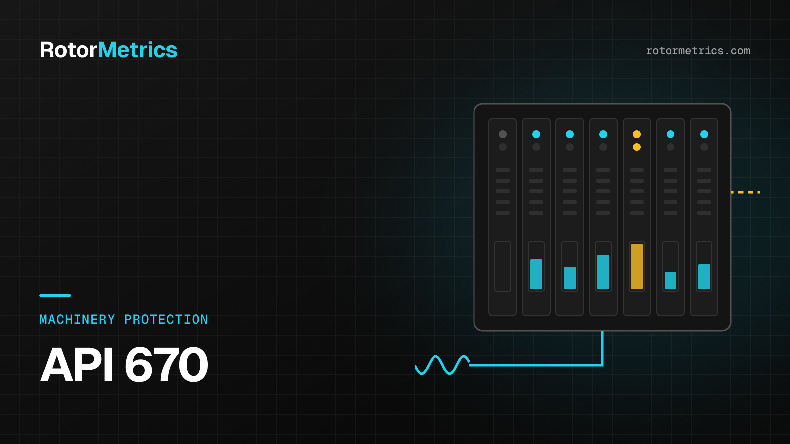
Proximitor signals are wired into a monitoring rack, such as the Bently Nevada 3500, probably the most widely installed platform in the industry. It houses vibration, position, temperature and overspeed monitors, plus relay and communication modules.
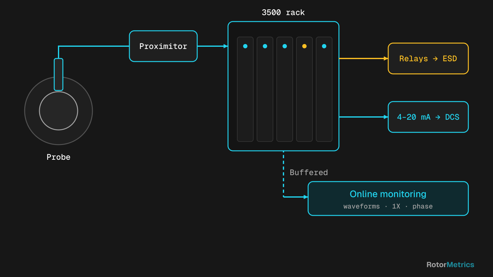
Each monitor computes an overall value (for example, direct vibration in mils or µm pp, or axial position in mils or mm), compares it against its setpoints, and drives relays. Those relays are wired to the emergency shutdown system or the machine control system, which actually executes the trip.
Alert and danger
Each channel normally has two setpoint levels:
| Level | Common name | What it does |
|---|---|---|
| First | Alert | Warns the operator; the machine keeps running |
| Second | Danger | Drives the trip relay, usually through voting logic |
Alert and danger values are set by the OEM or the end user based on machine design, bearing clearances and operating experience. There is no universal number.
Voting and time delays
A false trip on a large compressor train can cost almost as much as a real failure, so trip logic is designed to be both dependable and secure:
- Voting: instead of tripping on a single probe, channels are combined. For radial vibration, it is common to require confirmation from two probes; for overspeed, two-out-of-three voting across independent channels is the usual arrangement.
- Time delays: the value must stay above the danger setpoint for a short period, typically on the order of one to a few seconds, to reject spurious spikes.
- Transducer fault detection (Not OK): if a probe is disconnected or drifts out of its linear range, the monitor flags the channel as invalid and keeps it out of the trip logic instead of reading the fault as high vibration.
- Trip multiply: during startup, as the machine passes through its critical speeds, setpoints can be raised temporarily.
Buffered outputs: the doorway to diagnostics
Besides relays, monitors provide buffered outputs: a copy of the raw transducer signal, isolated so that a short or a bad connection on that output cannot compromise the protection function. They usually also provide 4–20 mA recorder outputs proportional to the overall value, and digital communications to the control system.
Buffered outputs are what let you connect an online condition monitoring system, or a portable analyzer, without touching the rack or changing its configuration.
Protection is not diagnostics
This is where most of the confusion lives. An API 670 system answers a single question very well: does the machine need to stop right now? An overall value and a pair of setpoints are all it needs for that.
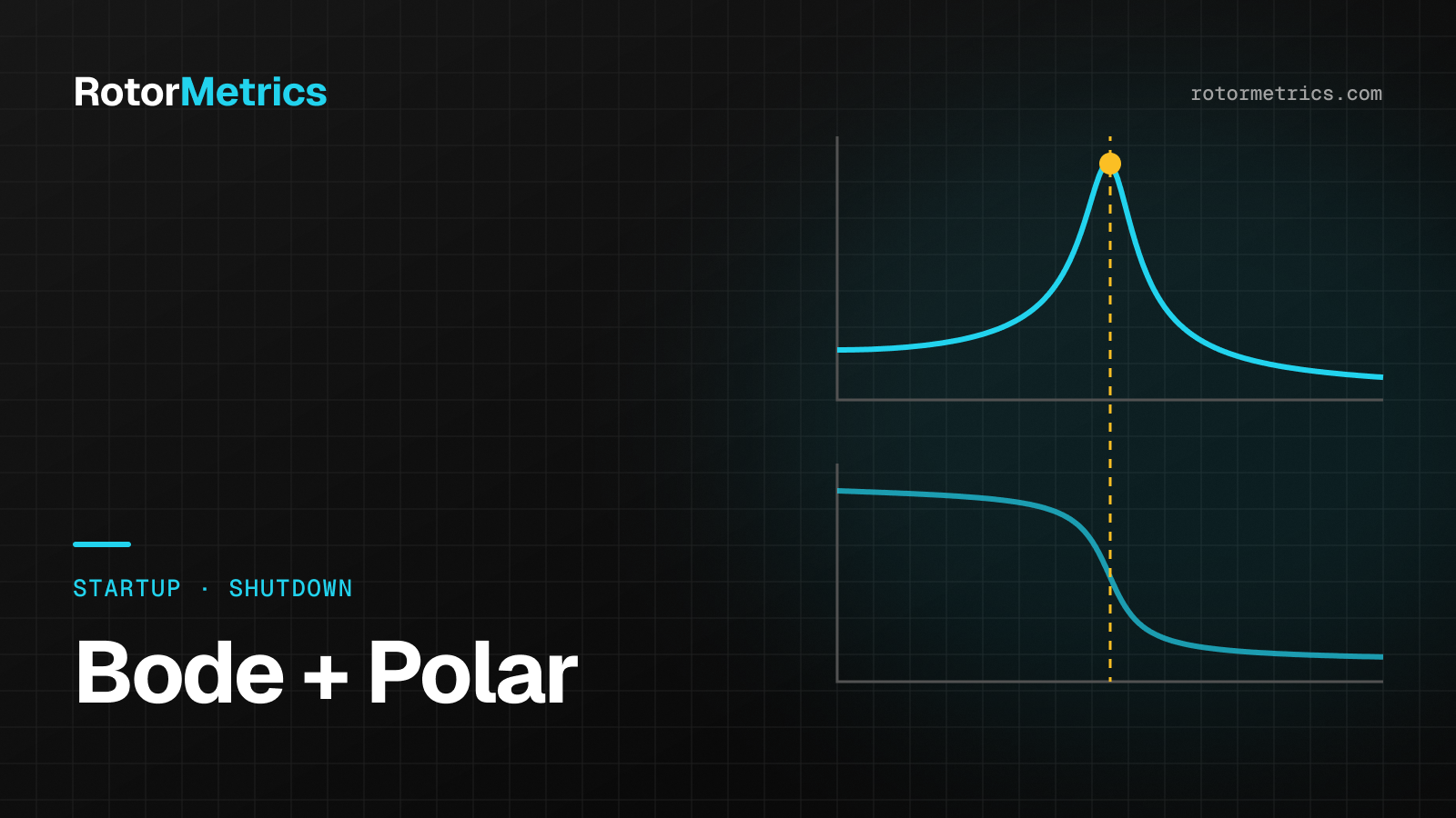
Diagnostics asks different questions: What is changing? Why? How fast? What should we do at the next outage? Answering those takes waveforms: spectra, orbits, 1X amplitude and phase, shaft centerline, Bode and polar plots. The same overall number can hide a growing unbalance, a misalignment that shifts with temperature, or a subsynchronous instability in its early stages.
Even more important, meaningful changes usually happen well below the alert setpoint. A machine that climbs from 0.8 to 1.4 mils pp over two weeks will not trigger anything if alert sits at 3 mils, yet it is telling you that something changed in the rotor.
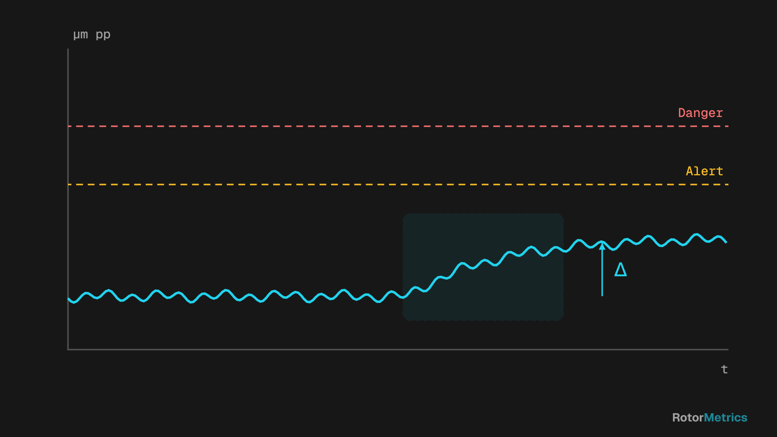
That is why API 670 protection and condition monitoring are not competing ideas. Protection is the last line of defense; diagnostics is what keeps you from ever needing it. To go deeper into reading that data, see our guides on how to interpret shaft orbits and on detecting turbocompressor faults with vibration analysis.
Getting more out of your API 670 system
- Verify the measurement chain at every major outage: probe gaps, cable lengths, connector condition and loop checks.
- Document your setpoints and revisit them after bearing changes or shifts in process conditions.
- Investigate Not OK events and false trips: they usually point back to installation or wiring.
- Don't use the alarm as a trending tool: store waveforms and compare against a healthy-machine baseline.
- Use the buffered outputs for diagnostics rather than opening the rack or changing its configuration.
How RotorMetrics does it
At RotorMetrics, we take the signal from your existing protection system, such as a Bently Nevada 3500, through its buffered outputs and without modifying it, always with your authorization and a plant representative on site. Your protection keeps working exactly as before. Our vibration specialists then review trends, spectra and orbits, and reach out when something changes, with a specific recommendation for your next maintenance window.
Sources
- American Petroleum Institute. API Standard 670: Machinery Protection Systems, 5th edition, 2014.
- Bently, D. E., and Hatch, C. T. Fundamentals of Rotating Machinery Diagnostics. Bently Pressurized Bearing Press, 2002.
- Eisenmann, R. C. Sr., and Eisenmann, R. C. Jr. Machinery Malfunction Diagnosis and Correction. Prentice Hall, 1998.
- ISO 20816-1:2016. Mechanical vibration — Measurement and evaluation of machine vibration — Part 1: General guidelines.
- ISO 7919 (Parts 1–5). Mechanical vibration of non-reciprocating machines — Measurements on rotating shafts and evaluation criteria (being superseded by the ISO 20816 series).
Want us to watch your machine?
Let's talk about your critical equipment and we'll show you how we'd monitor it.
Book a call