· 7 min read
Oil whirl vs. oil whip: fluid-film bearing instability explained
Why a component near 0.45X shows up in plain journal bearings, how to tell oil whirl from oil whip in spectra, waterfalls and orbits, and what to do next.
Andrés González
Fluid-film instability is one of the most deceptive problems in turbomachinery with hydrodynamic bearings. A machine can run smoothly for months, then a shift in oil temperature or bearing load brings up a subsynchronous component that grows fast. Overall vibration rises, but not always early enough to trip an alarm in time.
This article covers what oil whirl is, how it differs from oil whip, how to recognize each in the spectrum, waterfall and orbit, and how to respond.
The mechanism: a force that pushes sideways
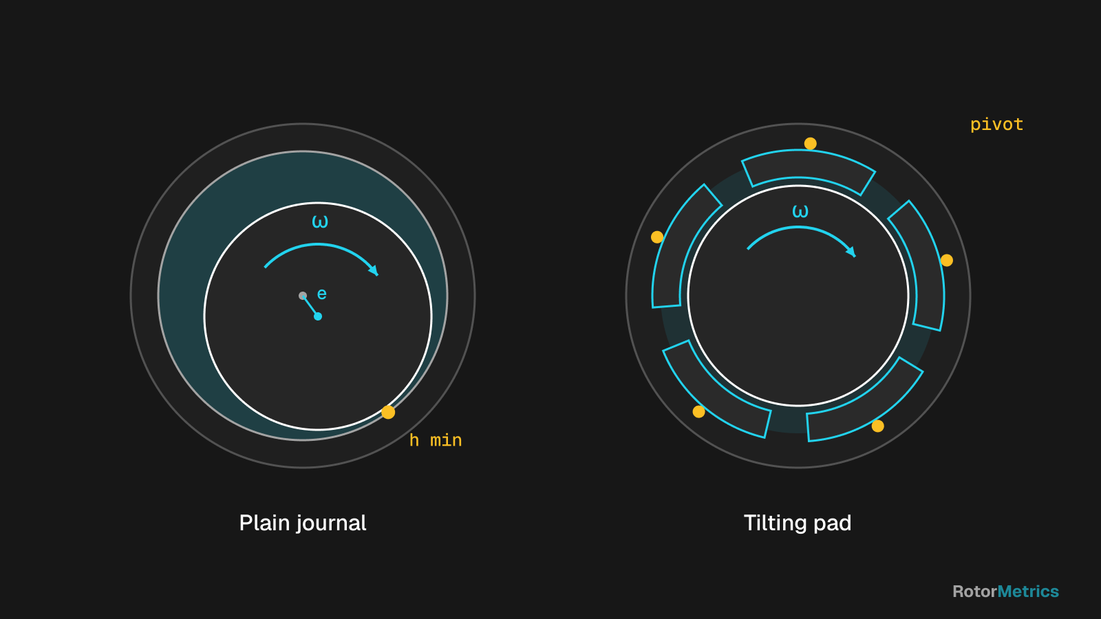
In a plain journal bearing the shaft does not run centered. Under load it moves off center and creates a converging oil wedge that builds pressure and carries the load. That offset is the eccentricity: the heavier the load, the closer the journal sits to the bearing wall.
The key point is that the oil film force does not act only opposite to the displacement. It also has a tangential component in the direction of rotation. Rotordynamicists model this as cross-coupled stiffness: push the shaft down and the film also pushes it sideways. That tangential force feeds forward precession, and once it exceeds the available damping, the rotor-bearing system goes unstable.
Why does the frequency sit just under half of running speed? The oil in the clearance is dragged along by the journal surface, while the bearing shell is stationary. Because of losses and pressure buildup, the average circumferential velocity of the fluid ends up slightly below half of shaft speed. That is why oil whirl typically shows up between 0.40X and 0.48X rather than at exactly 0.5X.
Oil whirl vs. oil whip
They are two stages of the same phenomenon, but the practical difference is significant.
Oil whirl: the subsynchronous component tracks running speed. As the machine speeds up, the frequency rises while keeping a nearly constant ratio, say 0.45X. Amplitude is often moderate and the bearing still controls the orbit.
Oil whip: once running speed reaches roughly twice the first critical speed, the whirl frequency coincides with that critical. From there on the component locks onto the first critical: the machine keeps accelerating, but the frequency stops rising. The rotor vibrates in its first mode with little damping, and amplitude can consume a large share of the bearing clearance. That means rubs, babbitt damage and shaft fatigue.
Whip typically shows hysteresis: once established, it often persists on coastdown well below the speed where it started.
| Feature | Oil whirl | Oil whip |
|---|---|---|
| Frequency | ~0.40–0.48X, proportional to speed | Fixed at the first critical |
| Response to speed | Rises with rpm | Stays put as rpm increases |
| When it appears | Lightly loaded bearing, any speed | Above ~2x the first critical |
| Amplitude | Moderate, may come and go | Large, can fill much of the clearance |
| Risk | Early warning | Damage in short order |
What it looks like in the data
Spectrum
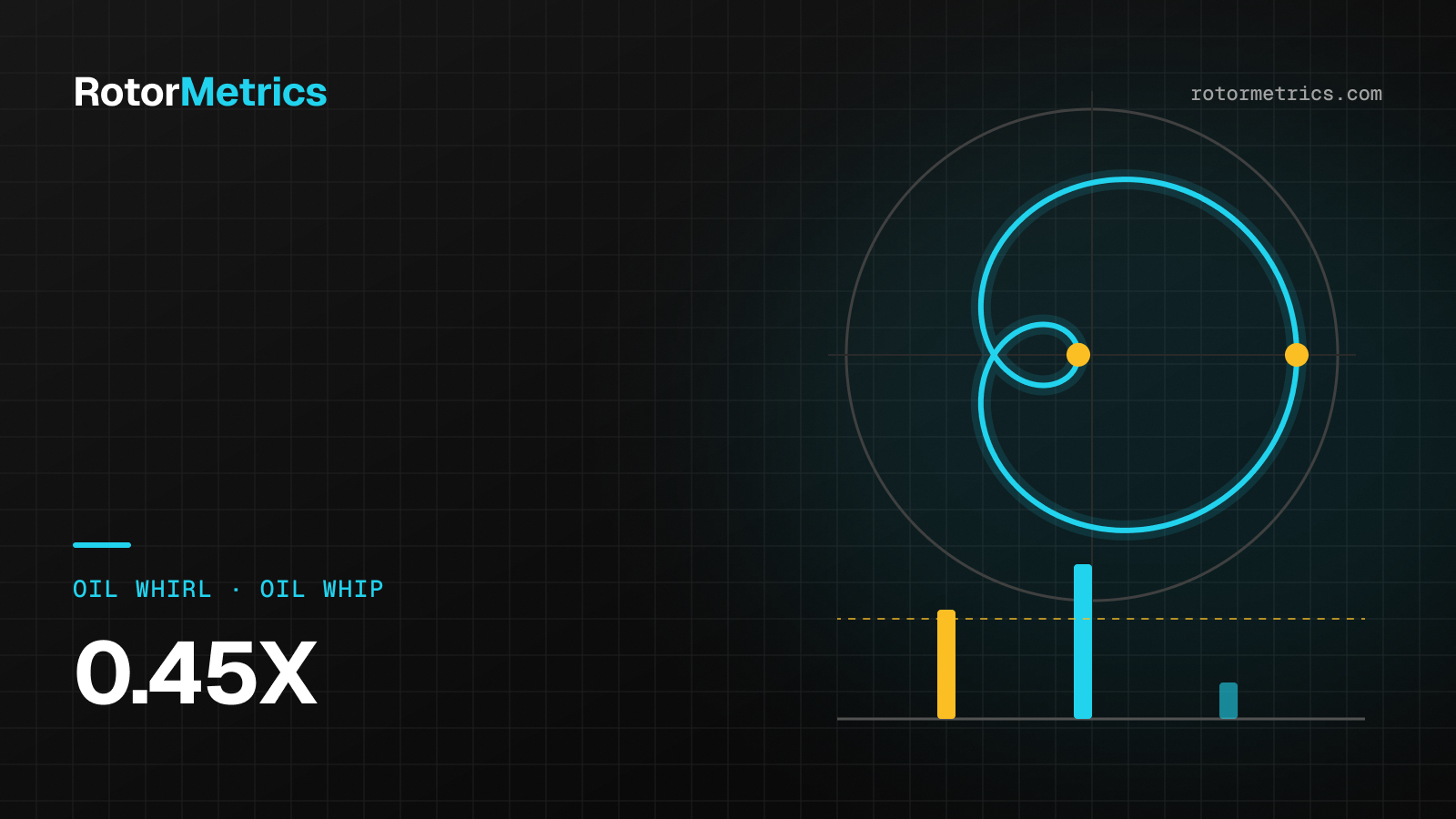
The spectrum shows a distinct subsynchronous peak, well separated from 1X. See how it combines with 1X and 2X and when it crosses the alarm level:
A quick check: compute the ratio of the peak frequency to running speed. If it stays around 0.43–0.47 at different speeds, think whirl. If the frequency in Hz stays fixed while speed changes, and it matches the critical you know from startup data, think whip.
Waterfall
The waterfall (or cascade) plot tells the story best. It stacks spectra taken at different speeds during a startup or coastdown:
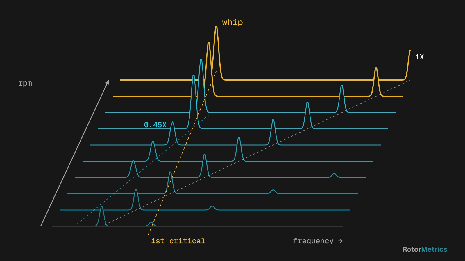
The 1X line climbs diagonally with speed. Whirl shows up as a second diagonal with less than half the slope. When that line reaches the first critical frequency, it bends and goes vertical: that is whip. To pin down the critical accurately, check the Bode and polar plots from the same transient; we cover that in startup and shutdown analysis with Bode and polar plots.
Orbit
With X and Y probes plus a Keyphasor, the unfiltered orbit shows internal loops: the shaft makes roughly two revolutions per cycle of subsynchronous precession. Precession is forward (in the direction of rotation), and the Keyphasor dots wander because the component is not an integer multiple of running speed.
The shaft centerline plot helps too. A journal floating near the bearing center, with low eccentricity and a large attitude angle, is a whirl candidate. For a refresher on loops, precession direction and phase marks, see how to interpret shaft orbits.
What drives it
Instability appears when cross-coupled stiffness wins over damping. In practice, the main drivers are:
- Light bearing load. Light rotors, vertical machines, load changes in gearboxes, or misalignment that unloads a bearing all leave the journal near center with low eccentricity. This is the classic setup.
- Oil viscosity. Colder, more viscous oil tends to center the journal and, in many cases, makes it less stable. A change in supply temperature or oil grade can be enough to trigger whirl.
- Clearance and wear. A worn or out-of-tolerance bearing changes the wedge geometry and the damping. Look at clearance and load together.
- Speed. Running faster, for example after a rerate, moves the machine closer to the whip threshold.
Not every subsynchronous peak is oil whirl
Before you replace a bearing, rule out other mechanisms below 1X:
- Rub. Can produce 1/2X, 1/3X and harmonics, with truncated or clipped orbits. A severe full annular rub can drive reverse precession (dry whip), which full spectrum plots help separate.
- Aerodynamic or seal instability. In high-pressure compressors, labyrinth seals and impeller aerodynamic forces also generate cross-coupling. It often locks onto the first critical just like whip, but amplitude tracks discharge pressure or process load more than oil temperature.
- Rotating stall. Shows up at low flow in centrifugal compressors, with a subsynchronous frequency that depends on flow conditions and is often visible on pressure or casing transducers too. It goes away once flow returns to a healthy range.
The key question is which variable moves it: oil temperature and bearing load (fluid-film), discharge pressure (seals or aero), flow (stall) or contact (rub). For an overview of these signatures side by side, see how to detect turbocompressor faults.
How to respond
Right away
- Confirm the measurement: the peak should show on both X and Y, with forward precession.
- Compare amplitude to bearing clearance. A subsynchronous component taking up a large fraction of diametral clearance calls for quick action, even with overall levels below alarm.
- Check the oil: supply temperature, pressure and flow. Raising supply temperature a few degrees, within OEM limits, often reduces whirl in plain bearings.
- Check the load: process changes, alignment shifts or gear load changes that may have unloaded the bearing.
- If it is whip, slowing down is not always enough because of hysteresis. Avoid sustained operation in that state and agree on a clear shutdown criterion with operations.
Design fixes
- Tilting pad bearings. Each pad pivots and aligns itself, so cross-coupled stiffness is practically zero. This is the standard answer for high-speed turbomachinery.
- Anti-whirl fixed geometries: lemon bore, offset halves, multilobe or pressure dam bearings. All aim to raise the effective film load.
- Adjust the load: correct alignment or load sharing between bearings, or shorten the bearing to raise unit loading.
- Stability analysis per API 617 and API 684 whenever operating conditions, seals or bearings change.
How RotorMetrics handles it
We take the signal from your existing protection system, such as a Bently Nevada 3500, without touching its configuration. We continuously watch the subsynchronous band, orbits and shaft centerline, not just overall levels. When a component near 0.45X appears, our analysts correlate it with oil temperature, load and speed, and send you a specific recommendation before it turns into whip.
Sources
- Bently, D. E., and Hatch, C. T. Fundamentals of Rotating Machinery Diagnostics. Bently Pressurized Bearing Press, 2002.
- Eisenmann, R. C. Sr., and Eisenmann, R. C. Jr. Machinery Malfunction Diagnosis and Correction. Prentice Hall, 1998.
- Muszynska, A. Rotordynamics. CRC Press, 2005.
- American Petroleum Institute. API RP 684: API Standard Paragraphs Rotordynamic Tutorial: Lateral Critical Speeds, Unbalance Response, Stability, Train Torsionals, and Rotor Balancing.
- American Petroleum Institute. API 617: Axial and Centrifugal Compressors and Expander-compressors.
- ISO 20816-1: Mechanical vibration — Measurement and evaluation of machine vibration — Part 1: General guidelines.
Want us to watch your machine?
Let's talk about your critical equipment and we'll show you how we'd monitor it.
Book a call